The Protocol Decision Belongs in the Specification
Dimming is the specification item most often deferred to the electrical contractor and then discovered to be incompatible. The sequence is familiar: fixtures are ordered with "dimmable" drivers, a control system is selected later on price or on a consultant's preference, and the two turn out to speak different languages. The result is either a re-driver exercise across the whole installation or a control system that dims in a narrow band at the top of its range, which is the compromise nobody photographs.
The fix is procedural rather than technical. Decide the control family at specification stage, write it into the luminaire schedule, and require the driver model and its dimming interface to be named in the quotation. Everything that follows in this guide is about making that decision early enough to be cheap.
The Control Families and What Each One Costs You
Control options sit on a spectrum from a dimming signal carried on the mains wiring to a fully addressed digital network. Each family has a different implication for wiring, driver selection, commissioning and future change.
| Approach | How it works | Best fit | What to watch |
|---|---|---|---|
| Mains dimming | The supply waveform is modified by a wall dimmer | Simple residential retrofits, small feature areas | Driver and dimmer must be matched; minimum load and a compatible dimming curve are essential |
| Analogue 0–10 V | A separate low-voltage signal pair sets the level | Single-zone commercial spaces where simplicity matters | No addressing, so zoning is fixed by wiring; polarity and isolation must be respected |
| Digital addressable | Each driver has an address and is individually controlled and monitored | Hotels, offices, retail and public buildings with zoning or reporting needs | Commissioning effort and the need for a control plan before first fix |
| Wireless mesh or app control | Fixtures or controllers form a network with no control cabling | Heritage interiors, refurbishments and spaces where extra cabling is impractical | Network resilience, gateway dependency and long-term support of the platform |
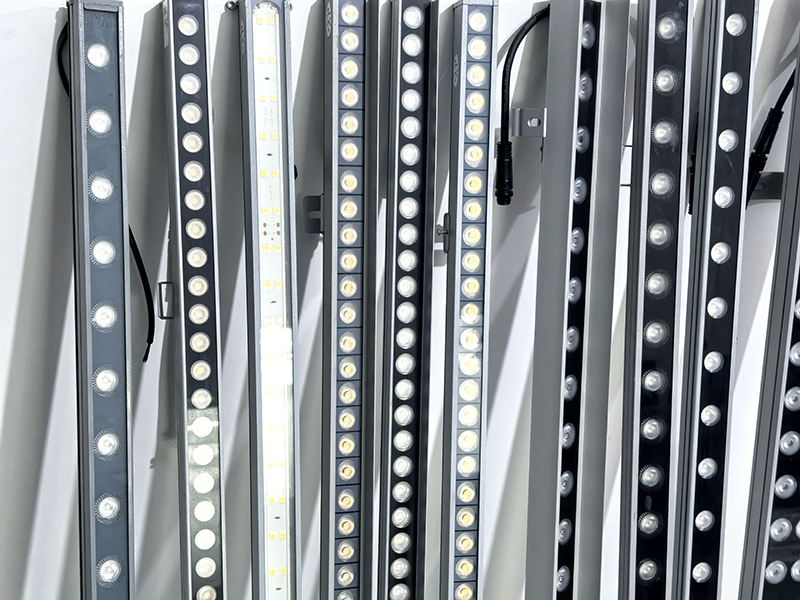
| Effects protocols | A serial protocol drives fast colour and dynamic scenes | Facades, entertainment and feature lighting only | Not appropriate for general illumination; a completely different driver ecosystem |
The choice is usually made on wiring cost against flexibility. A wired digital system costs more at first fix and less at every change afterwards; a wireless system costs less to install and places a longer-term dependency on the platform that runs it. Both are defensible, provided the reason is written down.
Driver Compatibility Is the Most Common Failure
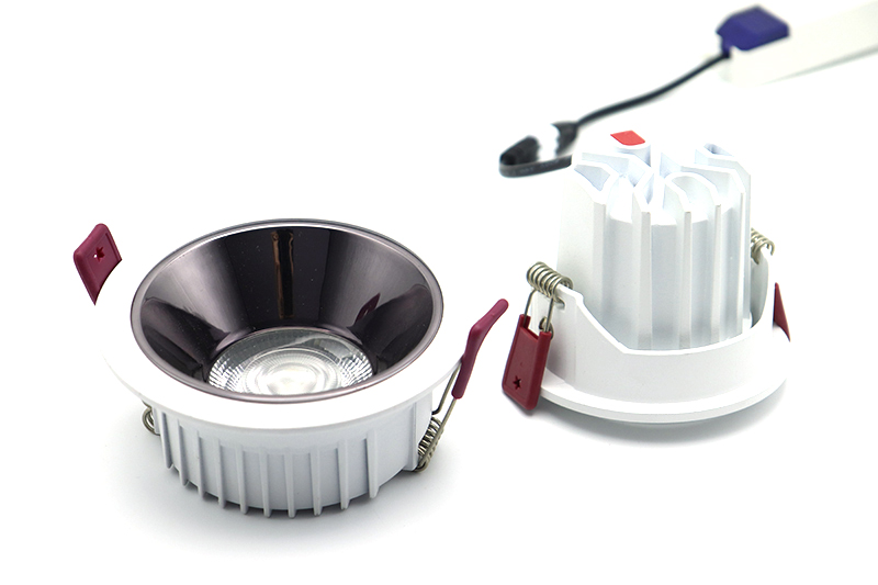
Almost every dimming problem traced back to a project is a driver problem, and almost every driver problem is a documentation problem. A driver is not generically dimmable; it supports particular interfaces, particular control curves and particular minimum loads. The table below sets out what each document answers.
| Item requested | What it answers | Asked of whom |
|---|---|---|
| Driver brand and model | Whether the specified interface is actually supported | Luminaire supplier, in writing, on the quotation |
| Dimming interface list | Which control families the driver can be wired to | Driver manufacturer datasheet |
| Compatibility list for proposed control gear | Whether this dimmer or controller has been tested with this driver | Control gear manufacturer, or the luminaire supplier as a written statement |
| Dimming curve and minimum level | How much of the control range is usable | Driver manufacturer |
| Minimum load per channel | Whether a single fixture will start and hold at low level | Dimmer or controller manufacturer |
| Inrush current and duration | Circuit protection sizing and how many fixtures fit on one circuit | Driver manufacturer, for the electrical design |
Where a supplier cannot name the driver, the specification should require it before the order is confirmed rather than after the first site visit, because a driver substitution is the change most likely to be made silently during a cost reduction exercise. It is also the change with the largest effect on how the finished installation behaves.
Inrush Current and Circuit Protection
LED drivers draw a brief high current at switch-on. In a circuit with a single fixture this is irrelevant; in a circuit with forty it is the reason a breaker trips at first energisation, usually on a cold morning, and then trips again every time the circuit is switched from the panel. The effect compounds with driver capacitors and is aggravated when a circuit is protected by a device with a fast response.
The remedy is arithmetic done in advance: the manufacturer's stated inrush current and its duration, multiplied by the number of fixtures per circuit, checked against the protective device's rating and type. Where a circuit is close to the limit, splitting it or specifying a device with a suitable characteristic is a low-cost decision before installation and a disruptive one afterwards. For projects with frequent switching, or with a control system that groups fixtures, this calculation should be part of the electrical design rather than a site fix.
Minimum Load and the Bottom of the Range
A dimming system that performs beautifully at 80% and flickers at 8% is not dimmable in any useful sense. Two specifications prevent it. The first is the minimum load of the dimmer or controller, which must be met by the total connected load on that channel; a single fixture on a channel rated for many times that load may not start reliably at all. The second is the dimming curve, which determines how much of the control range produces visible change. A driver with a curve that compresses most of its range into the top third will feel to the occupant like a switch with two settings.
Both facts are stated by the driver manufacturer and both should be requested as part of the luminaire documentation, since the same fixture from two production runs can carry different drivers.
Flicker Across the Whole Dimming Range
Flicker is specified at full output far more often than it is measured across the dimming range, which is precisely where it becomes visible. As the drive current falls, the ripple in the output can rise, and rooms with wide dimming — a hotel ballroom, a restaurant, a residential living space used in the evening — are where the effect is noticed most. The specification should therefore state the flicker requirement at the lowest dimming level the space will actually use, not at 100%.
The same requirement should extend to camera-visible spaces. A dimmed retail display or a hospitality interior may be filmed, and a flicker level that is comfortable to the eye can still produce banding on video. Where that is a possibility, it belongs in the brief.
Scenes, Zoning and the Control Layer
Zoning is an operational decision that has to be made before the wiring is designed, because it determines the control topology and the cable routes. The workable questions are: which areas will be operated independently, what scenes each area needs, who will change the scenes after handover, and whether any area needs to be measured or reported on. Each answer changes the specification, and each costs significantly more to accommodate retrospectively.
It is also worth naming who owns the control layer after handover. If the answer is a software platform, the project needs a statement about the licence, the hosting and the support term, because an unreachable gateway turns an addressable installation into a manual one.
Writing the Control Requirement Into the Order
- Control family — named per area, with the reason recorded in the specification
- Driver brand and model — named in the quotation, with its dimming interface stated
- Compatibility list — obtained in writing for the proposed control gear
- Minimum load per channel — checked against the connected load, not assumed
- Dimming curve — and the usable bottom of the range agreed in advance
- Flicker requirement — stated at the lowest level the space will actually use
- Inrush current — provided for the electrical design, with circuit protection checked
- Zoning and scenes — fixed before first fix, not rearranged after commissioning
- Spare drivers — held from the same production batch as the installation
Commissioning and Handover
Commissioning is the point at which the specification is tested, and it is routinely compressed because it sits at the end of the programme. Two documents make it quick and durable: a schedule of the scenes and levels the system is expected to deliver, and a record of the addresses, settings and firmware versions as installed. With those on file, an adjustment in year two is a ten-minute task; without them, it is a site investigation.
For addressable systems, the handover record should also state how the installer intends to maintain the system if a driver is replaced years later, since a replacement driver will need addressing to the same configuration. This is the practical reason to hold spare drivers from the same batch, and to keep the configuration file with the building documentation rather than on a laptop that leaves site.
Summary
Choose the control family before the luminaire schedule is issued, name the driver model in the quotation, and write the compatibility, minimum load, dimming curve, flicker and inrush requirements into the order rather than leaving them to the electrical contractor. Then commission against a written scene schedule and hand over the configuration record. An installation specified this way behaves the same in year three as it did on handover day, which is the whole point of controlling it. Further guides sit in our buying guides, and the related photometric questions are covered with our product knowledge articles.